Manipulation, Motion & Sample Handling
Thermionics offers a variety of advanced UHV sample handling components, UHV heaters, manipulators, and multi motion feedthroughs for precise positioning, heating, cooling, and transferring of samples. Designed to meet the exacting demands of high-performance research, our sample handling systems and UHV sample manipulators provide smooth, accurate control for scientific and industrial environments.
-
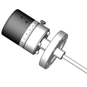
Feedthroughs (32)
-
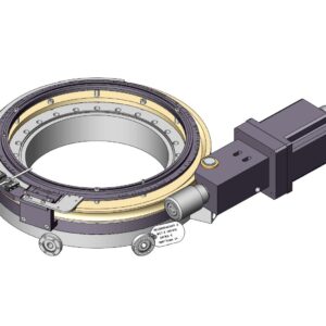
RNN Rotary Seals (8)
-
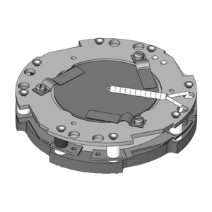
Sample Handling (25)
-
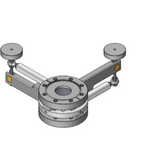
Tilt Stages (4)
-
XY Manipulators (4)
-
XYZ Manipulators (7)
-
Z Manipulators (7)