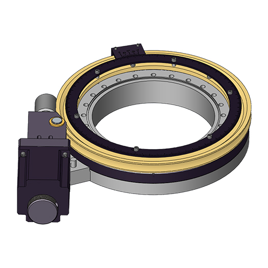
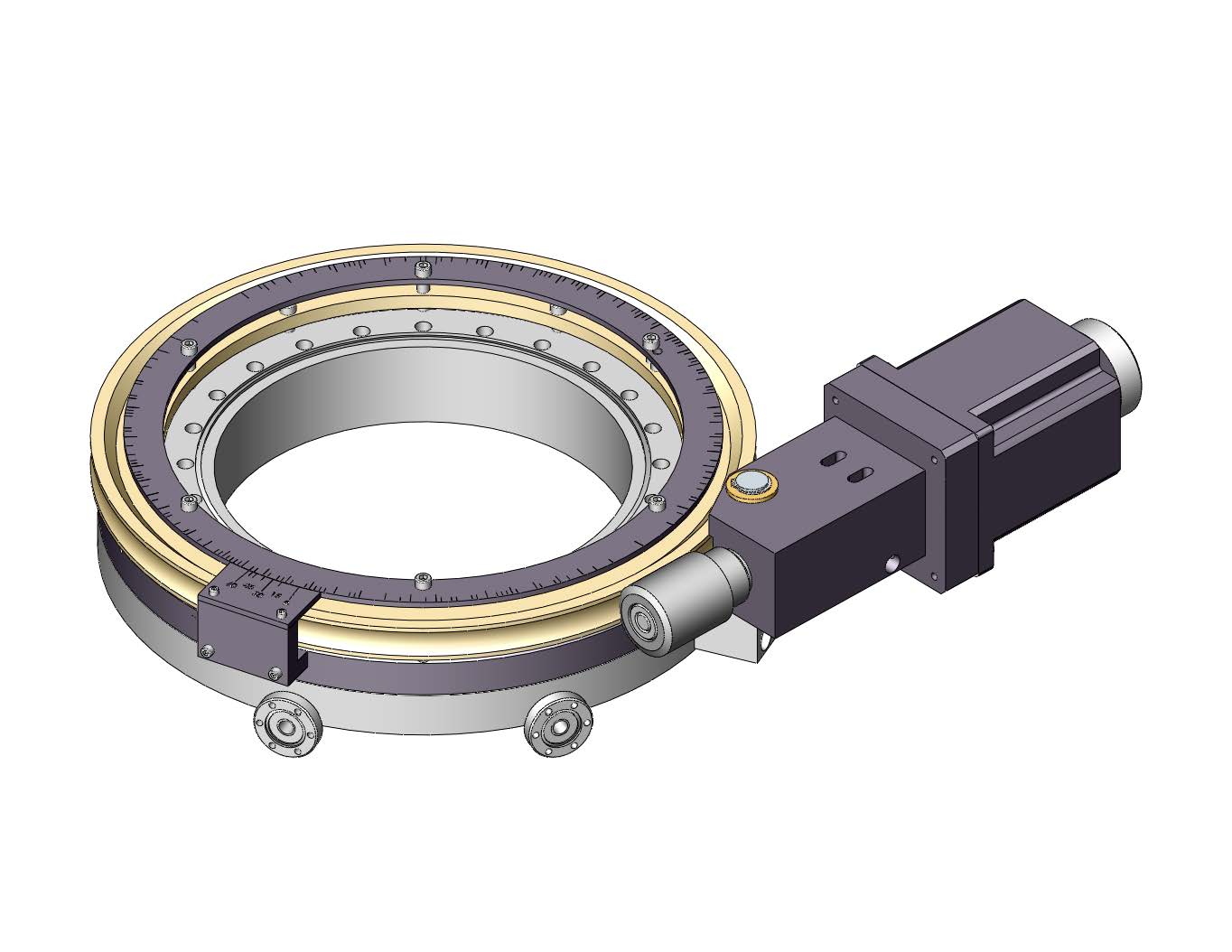
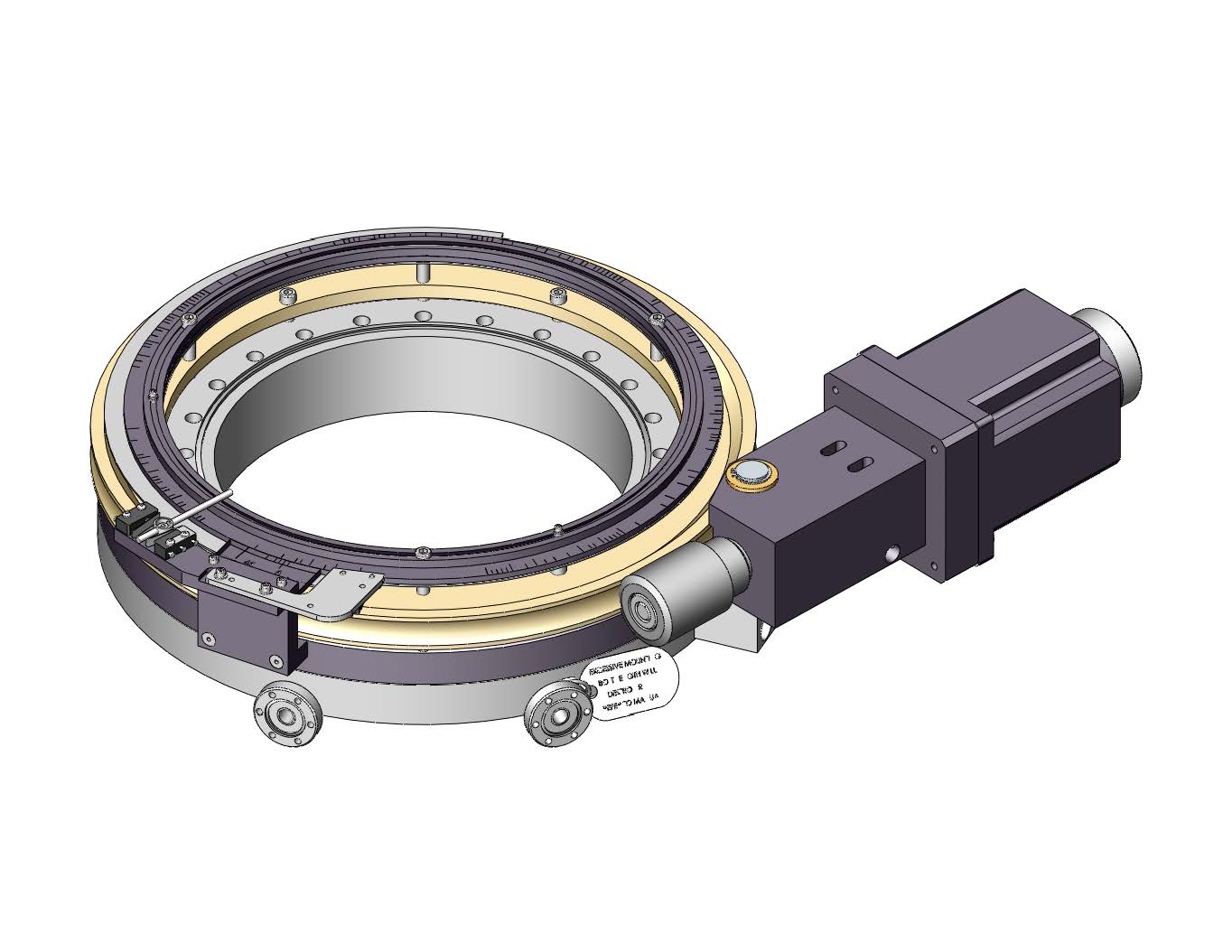
RNN™ Series Differentially Pumped Rotary Seal
Differentially pumped rotary seals (RNNs) provide 360° of continuous rotary freedom through the vacuum wall of a UHV system. The RNN has two stages of differential pumping isolated by graphite-impregnated, expanded, Teflon® seals on special sealing surfaces. A preloaded ball bearing set accurately controls the rotating stage position.
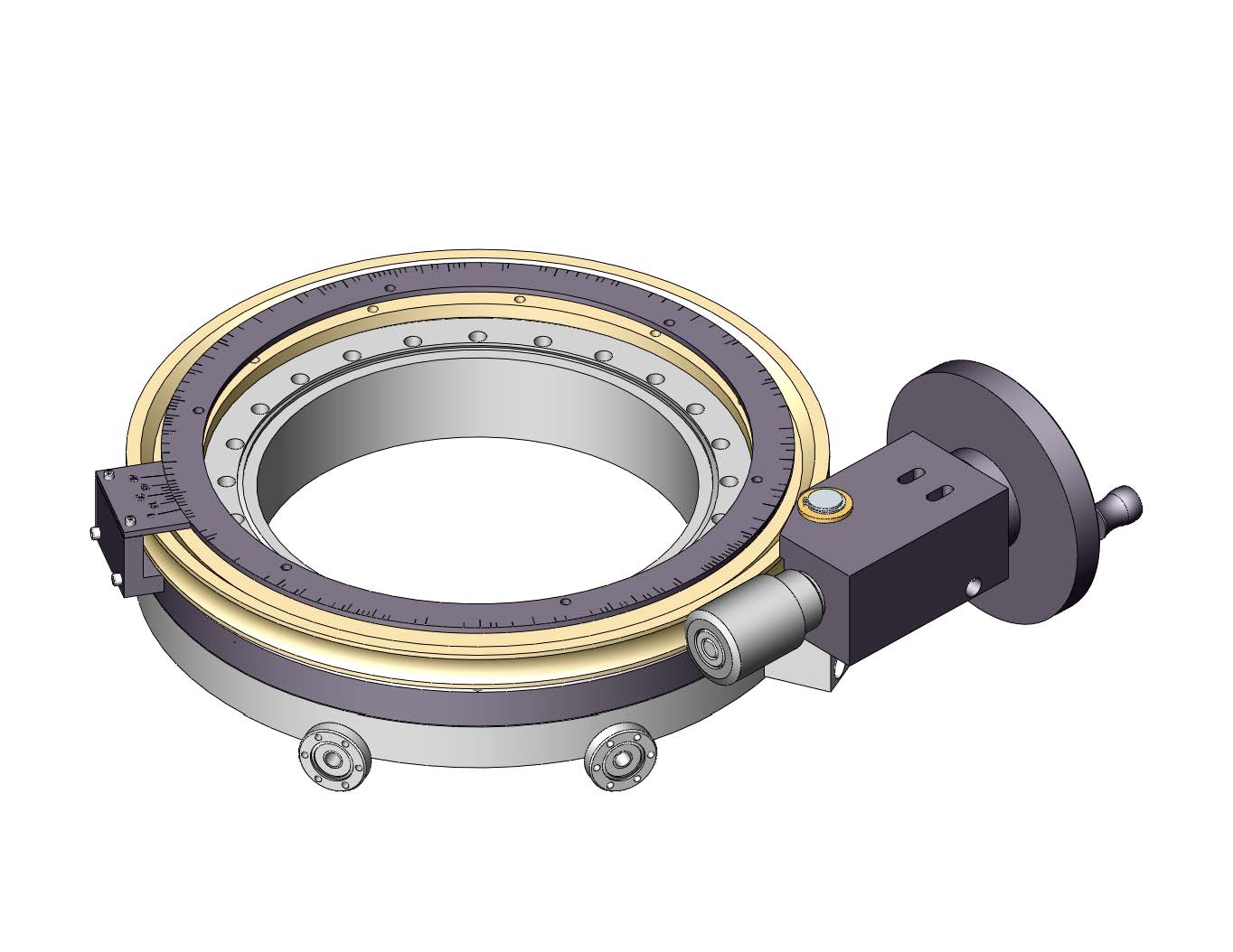
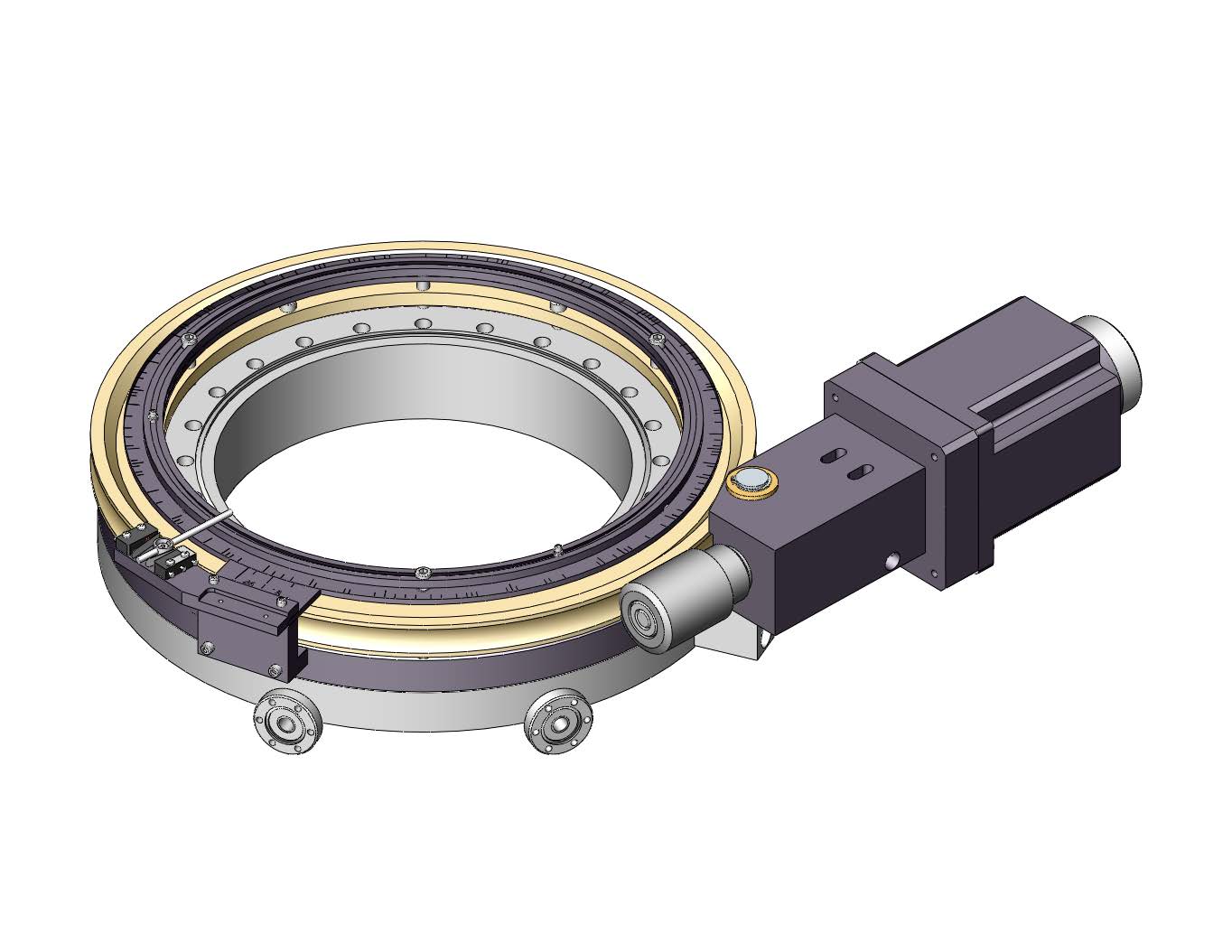
RNNs are available with a worm drive fine adjust option. This allows for easier and more accurate angle adjustment. RNNs are also available with anti-backlash stepping or synchronous motor drive.
RNNs with up to 12″ I.D. are listed. Larger I.D.s have been built with excellent performance. Please consult factory for special applications.
Specifications
- Models with clear inside diameters of 1.53″ to 12″ standard, larger sizes on request
- Bakeable to 150°C
- Stationary and rotation flanges, tapped
- Thickness approximately that of two ConFlat-type flanges
- 2 stage differentially pumped
- Base pressures in 10-11 Torr range
- 0–360° scale with Vernier, standard
Typical Performance Specifications for RNN-400 and larger models
- Resolution: <0.004°
- Repeatability: <0.008°
- Backlash: <0.035°
Readability Specifications
- Standard scale: 1.0°
- Mechanical counter: 0.1°
- Microstepped motor drive required for maximum resolution
Options
- Fine adjust worm drive
- Digital read-out on fine adjust, 0.1° read-out, mechanical, nonresetable
- Mechanical counter option available
- Anti-backlash stepping motor drive 0.018° per full step (0.0225°/full step on RNN-150/MS), with manual knob
- Custom pumpout tube lengths and crank shaft lengths on /FA units available
Payloads
The standard maximum payloads are listed below. Larger loads may be handled under specific applications. Please consult the factory for custom applications.
- The center of gravity of the payload is within “X” of the polar axis of the unit, where X is equal to 10% of the RNN I.D.
- The center of gravity of the payload is within “Y” distance of the rotating flange on the horizontal mounted units, where Y is the flange I.D.
- The overall maximum size “A” of the payload outside vacuum is:
Vertical operation: 7 x flange O.D. Horizontal operation: 5 x flange O.D. Inverted operation: 7 x flange O.D.
| Model No. | Vertical | Horizontal | Inverted |
| RNN-150 | 54 lbs | 30 lbs | 45 lbs |
| RNN-250 | 90 lbs | 38 lbs | 70 lbs |
| RNN-400 | 144 lbs | 66 lbs | 110 lbs |
| RNN-600 | 180 lbs | 84 lbs | 140 lbs |
| RNN-800 | 200 lbs | 91 lbs | 160 lbs |
| RNN-1000 | 370 lbs | 160 lbs | 280 lbs |
| RNN-1200 | 430 lbs | 200 lbs | 350 lbs |
Payload Location
Table 1. RNN Series Differentially Pumped Rotary Seals
(includes a removeable adjustment wrench)
| I.D. | Flange O.D. |
A | B | C | D | E | F | G | H | Model No. |
| 1.53 | 2.75 | 4.50 | 2.99 | 1.0 | 3.18 | 2.75 | .49 | .13 | 60° | RNN-150 |
| 1.53 | 2.75/6 1 | 6.00 | 2.99 | 1.34 | 3.33 | 2.75 | .15 | .13 | 45° | RNN-150/6 |
| 2.53 | 4.5 | 5.75 | 3.64 | 1.36 | 3.58 | 4.50 | .49 | .03 | 45° | RNN-250 |
| 2.53 | 4.5/6 1 | 6.00 | 3.64 | 1.52 | 3.71 | 4.50 | .33 | .03 | 45° | RNN-250/6 |
| 4.03 | 6 | 7.75 | 4.57 | 1.68 | 4.34 | 6.02 | .37 | .06 | 45° | RNN-400 |
| 6.03 | 8 | 10.25 | 6.16 | 1.74 | 5.70 | 8.00 | .42 | .13 | 54° | RNN-600 |
| 8.00 | 10 | 12.05 | 7.03 | 1.94 | 6.70 | 10.00 | .42 | .13 | 45° | RNN-800 |
| 10.00 | 13.25 | 15.75 | 8.81 | 2.37 | 8.50 | 13.28 | .29 | .13 | 24° | RNN-1000 |
| 12.00 | 14 | 20.00 | – | 3.34 | – | – | – | – | – | RNN-1200 |
Dimensions in inches
1 Signifies mounting flange sizes respectively
Table 2. RNN/FA Differentially Pumped Rotary Seals with Fine Adjust 1

| I.D. | Flange O.D. |
A | B | C | D | E | F | G | H | I | Drive Ratio |
Model No. |
| 1.53 | 2.75 | 5.13 | 3.38 | 1.00 | 4.95 | 2.75 | .49 | 0.37 | 60° | 3 | 80:1 | RNN-150/FA |
| 1.53 | 2.75/6 2 | 6.00 | 3.84 | 1.34 | 5.32 | 2.75 | .15 | 0.37 | 45° | 3 | 100:1 | RNN-150/6/FA |
| 2.53 | 4.5 | 6.38 | 4.20 | 1.36 | 6.11 | 4.50 | .49 | 0.41 | 45° | 3 | 100:1 | RNN-250/FA |
| 2.53 | 4.5/6 2 | 6.38 | 4.20 | 1.52 | 6.11 | 4.50 | .33 | 0.41 | 45° | 3 | 100:1 | RNN-250/6/FA |
| 4.03 | 6 | 8.50 | 8.25 | 1.68 | 9.28 | 6.02 | .37 | 0.54 | 45° | 4 | 100:1 | RNN-400/FA |
| 6.03 | 8 | 10.25 | 8.50 | 1.74 | 9.93 | 8.00 | .42 | 1.10 | 54° | 5 | 100:1 | RNN-600/FA |
| 8.00 | 10 | 12.75 | 9.56 | 1.94 | 11.50 | 10.00 | .42 | 1.10 | 45° | 5 | 100:1 | RNN-800/FA |
| 10.00 | 13.25 | 17.00 | 11.86 | 2.37 | 17.25 | 13.28 | .29 | .91 | 24° | 7 | 100:1 | RNN-1000/FA |
| 12.00 | 14 | Consult Factory | RNN-1200/FA | |||||||||
Dimensions in inches
1 The fine adjust units utilize worm drive and are dynamic anti-backlash on RNN-400 and larger models. They come with large knobs and crank handles.
2 Signifies mounting flange sizes respectively
Table 3. RNN/MS or /MY Differentially Pumped Rotary Seals with Anti-Backlash /MS Stepping or /MY Synchronous Motor Drive 1
I.D. |
Flange
O.D. |
A |
B |
C |
D |
E |
F |
G |
H |
I |
Drive
Ratio |
Model
No. |
| 1.53 | 2.75 | 5.13 | 10.00 | 1.00 | 9.97 | 2.75 | .49 | 0.74 | 60° | 3.39 | 80:1 | RNN-150/MS or /MY |
| 1.53 | 2.75/6 2 | 5.13 | 10.00 | 1.34 | 9.97 | 2.75 | .15 | 0.74 | 45° | 3.39 | 100:1 | RNN-150/6/MS or /MY |
| 2.53 | 4.5 | 6.38 | 10.10 | 1.36 | 8.30 | 4.50 | .49 | 0.41 | 45° | 3.39 | 100:1 | RNN-250/MS or /MY |
| 2.53 | 4.5/6 2 | 6.38 | 10.10 | 1.52 | 8.30 | 4.50 | .33 | 0.41 | 45° | 3.39 | 100:1 | RNN-250/6/MS or /MY |
| 4.03 | 6 | 8.50 | 9.77 | 1.68 | 11.69 | 6.02 | .37 | 0.54 | 45° | 3.39 | 100:1 | RNN-400/MS or /MY |
| 6.03 | 8 | 10.20 | 10.13 | 1.74 | 11.69 | 8.00 | .42 | 1.10 | 54° | 3.39 | 100:1 | RNN-600/MS or /MY |
| 8.00 | 10 | 12.75 | 11.39 | 1.94 | 11.69 | 10.00 | .42 | 1.10 | 45° | 3.39 | 100:1 | RNN-800/MS or /MY |
| 10.00 | 13.25 | Consult Factory | RNN-1000/MS or /MY | |||||||||
| 12.00 | 14 | Consult Factory | RNN-1200/MS or /MY | |||||||||
| 18.00 | 24 | Consult Factory | RNN-1800/MS | |||||||||
| 24.00 | 34 | Consult Factory | RNN-2400/MS | |||||||||
Dimensions in inches
1 The motor drive units utilize worm drive and are all dynamic anti-backlash with hand knobs at the rear of the motor
2 Signifies mounting flange sizes respectively
Options
Mechanical Counter
- Add digital read-out to fine adjust or motor drive unit
- 0.1° read-out, mechanical, nonresetable
- Viewable from the side
- Solution to difficulty caused by equipment mounted to platform obstructing view of degree scale
- When /MC option is selected the Vernier scale is not included
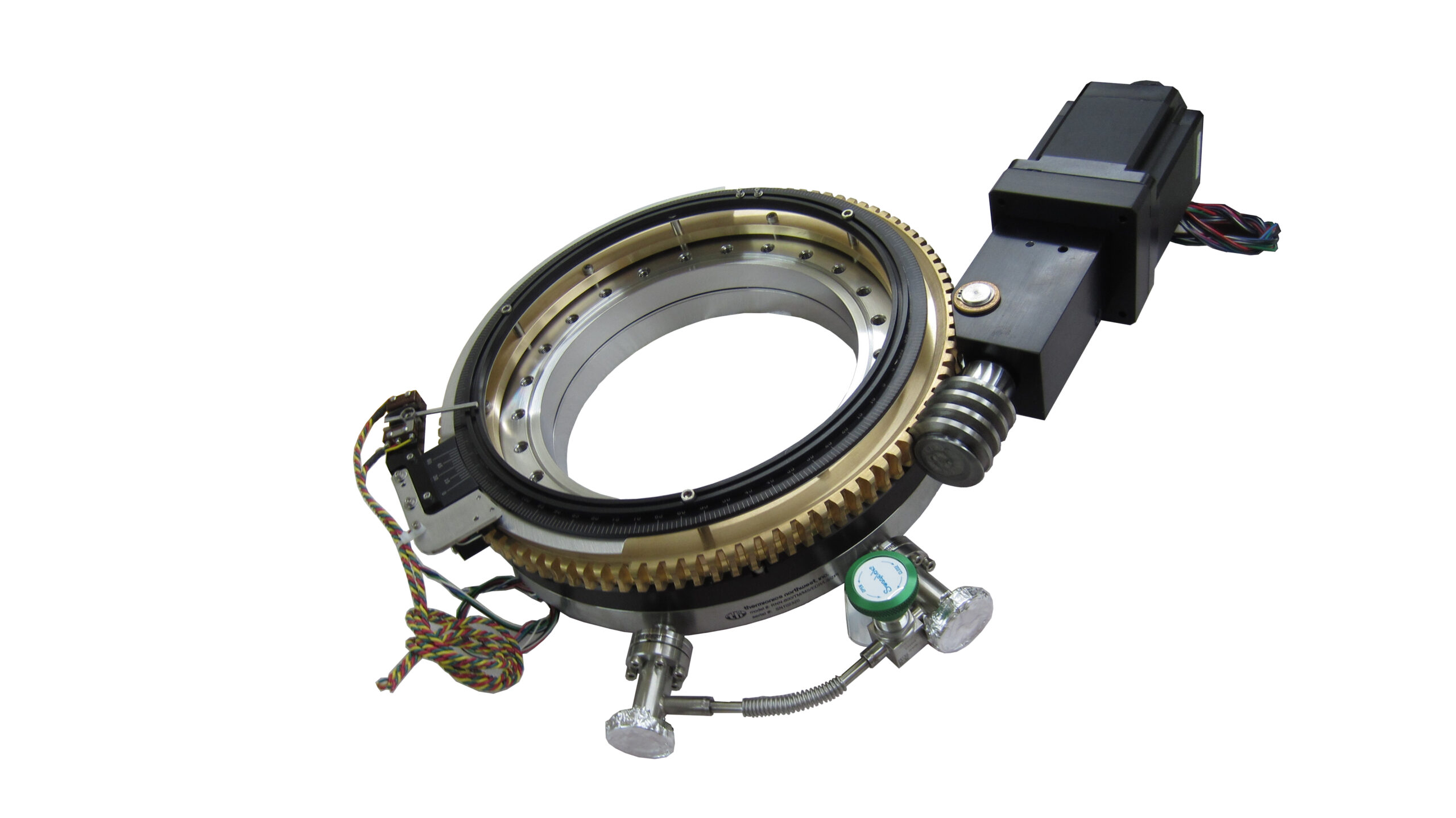
Valve Manifold System
- Allows first stage pump to evacuate second stage pump
- Includes: two modified 1.33″ O.D. flange nipples; BVV-025 bakeable valve; flexible metal plumbing
- Assembled on RNN platform
2 l/s Appendage Ion Pump Assembly
- Use with valve manifold system
- Allows continuous pumping of RNN
- Includes Alnico magnet
- Requires ion pump control unit
Ion Pump Control Unit
- For use with 2 l/s appendage ion pump assembly
- Power input: 115 VAC, 60 Hz or 230 VAC, 50 Hz (specify with order)
- Power output: 5 kV DC
- Includes HV coax cable and power cord